Common Path
Decker | Slit | User Filter Assembly | Polarimeter Module | Dichroics and MirrorDecker
The decker is a long reflective plate which overlies the slit. The observer may select a variety of options including slits of varying length, rectangular blockers of varying widths, circular blockers of various diameters, a set of non-symmetric slots for bizarre sky subtraction schemes, or the decker may be withdrawn completely for unobstructed direct imaging. One positon called "the finger" places the end of the rectangular blocker just off of the slit (for slits 1" or less wide) for use as a reference for positioning objects at the center of the slit length (it's usually a convenience in the reduction if everything falls along the same rows). Notice that there are two full length positions (1 and 10). Position 1 may be used for either spectroscopic or direct. Position 10 will allow a full length slit for "normal" slit sizes, but will be paritally obstructed by adjacent portions of the decker if the slit is fully open, as for a direct window. Position 10 is closer physically to the normally used finger (position 11), so if you are switching between large and small spectroscopic slits, you may wish to use these adjacent positions. In fact the decker moves very rapidly, so 1 will work just as well. But don't use 10 for directs. A full-length decker is 145 arcseconds, which is 333 pixels on either the red or blue side detector (both have 15 micron pixels). This corresponds, of course, to the full length of the slit itself. The decker slide is presently configured as follows:| Position | Name | Encoder number | Notes |
|---|---|---|---|
| 0 | Home | 0 | |
| 1 | Open | -4375 | For direct imaging |
| 2 | Asymmetric slots 1 | -2942 | |
| 3 | Asymmetric slots 2 | -2601 | |
| 4 | Asymmetric slots 3 | -2259 | |
| 5 | Asymmetric slots 4 | -1918 | |
| 6 | 1 arcsec long | -1398 | For slits up to 14" wide |
| 7 | 2 arcsec long | -1228 | For slits up to 14" wide |
| 8 | 15 arcsec long | -1058 | For slits up to 14" wide |
| 9 | 30 arcsec long | -885 | For slits up to 14" wide |
| 10 | 60 arcsec long | -712 | For slits up to 14" wide |
| 11 | Spect | -170 | Full length, not for directs |
| 12 | Finger | -75 | End of blocker in slit for slits larger than 1" wide |
| 13 | 2 arcsec rectangular blocker | -29 | For slits up to 9.5" wide |
| 14 | 4 arcsec rectangular blocker | 108 | For slits up to 9.5" wide |
| 15 | 6 arcsec rectangular blocker | 217 | For slits up to 9.5" wide |
| 16 | 8 arcsec rectangular blocker | 335 | For slits up to 9.5" wide |
| 17 | 9 arcsec circular blocker | 1154 | * |
| 18 | 6 arcsec circular blocker | 2348 | * |
| 19 | 3 arcsec circular blocker | 3522 | * |
| *The occulting disks are alumininized spots on a quartz plate which is not AR coated. Occulting disks are designed for use in direct imaging mode and do not line up with the slit. To occult objects in spectroscopy mode, use the rectangular blocker. | |||
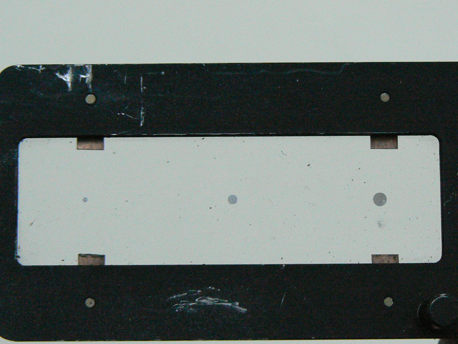
Figure 1: Decker Occulting Spots (for Direct Imaging, not Spectroscopy), 3, 6, and 9 arcsec diameters.
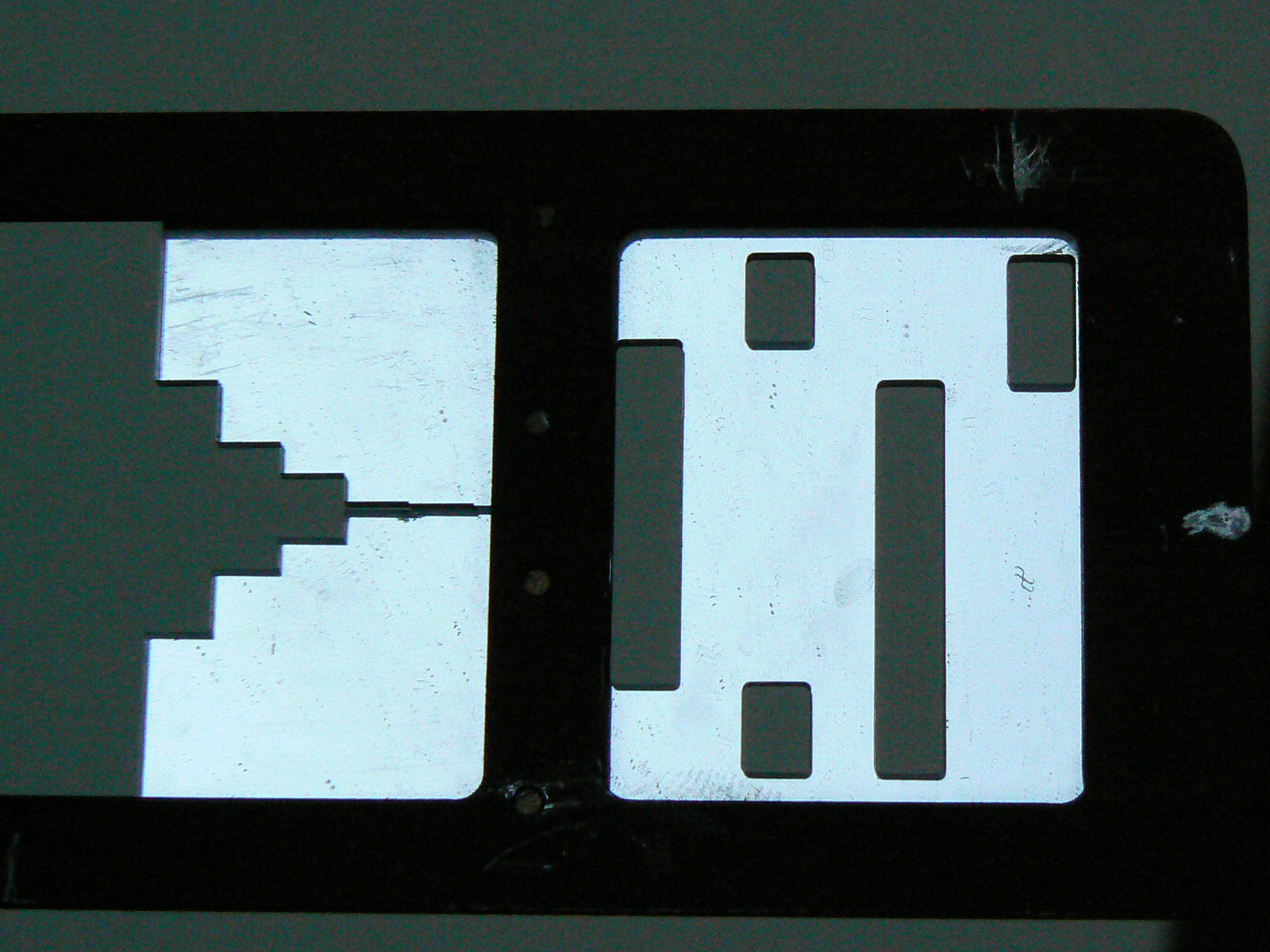
Figure 2: Slit Length Settings (left) of Spect, 60, 30, 15, 2, and 1 arcsec long, and Assymetric Slots (right).
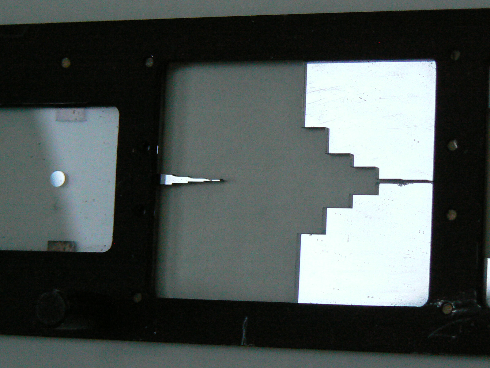
Figure 3: Finger (Rectangular Blocker) on left, Slit Length Settings (right).
Slit
The aluminized slit opens bilaterally, and the smallest available step is a tiny fraction of a pixel. For convenience, the most commonly used slit sizes may be selected from the spectrograph controller simply by selecting the size in arcsecs according to the table below. Alternatively, you may enter the desired slit width in arcseconds from the 'Other...' option in the Slit selection menu. Minimum slit size is set to 0.4 arcsec. Remember that you need at least a two pixel slit to minimize aliasing problems with narrow emission lines.| Scales and Conversions |
|---|
| scale at slit = 3.86 arcsec/mm |
| 1mm = 3.86 arcsec = 8.885 pixels (for 15 micron pixel size) |
| 1 pixel = 0.43 arcsec = 0.1126 mm (for 15 micron pixel size) |
| Position | Name | Encoder Number |
|---|---|---|
| 0 | Home | 0 |
| 1 | Open | -34344 |
| 2 | 0.5 arcsec | 3989 |
| 3 | 1.0 arcsec | 3857 |
| 4 | 1.5 arcsec | 3724 |
| 5 | 2.0 arcsec | 3591 |
| 6 | 2.5 arcsec | 3459 |
| 7 | 3.0 arcsec | 3326 |
| 8 | 4.0 arcsec | 3061 |
| 9 | 5.0 arcsec | 2796 |
| 10 | 9.0 arcsec | 1734 |
| Other... | User enters desired slit size in arcsec |
User Filter Assembly
There are three stacked filter wheels called, from top to bottom, the upper, lower, and user wheels. One position of each wheel (position 0) is always empty. Filters in the top three wheels will affect both beams of the spectrograph. If you want to use different filters on the two sides, they must be installed in the holders in front of the cameras. Since these later filters are in the collimated beam they must be bigger than 3.5 inches in diameter in order to avoid vignetting for direct imaging (a 2" square filter will reduce the effective aperture to about 1-meter; if this is your plan, it would surely be more politic to ask for one-meter time in the first place). Order separating filters should not be necessary in typical double-beam use, except in the far red.| Upper Filter Wheel | |||
|---|---|---|---|
| Position | Name* | Encoder number | |
| 0 | Home | 0 | |
| 11 | Open | 1275 | |
| 12 | None | 2299 | |
| 13 | Spinrad NS** | 3323 | |
| 14 | ND5.0 | 4347 | |
| 15 | ND1.25 | 5371 | |
| 16 | ND7.5 | 6395 | |
| 17 | ND2.5 | 7419 | |
| 18 | calcite prism | 251 | |
|
*ND values are in magnitudes. **Spinrad night sky filter pass band is ~6100 - 7600 A | |||
| Lower Filter Wheel | |||
|---|---|---|---|
| Position | Name | Encoder number | |
| 0 | Home | 0 | |
| 11 | Open | 1435 | |
| 12 | BG14++ | 2459 | |
| 13 | OG570 | 3483 | |
| 14 | ND6.25 | 4507 | |
| 15 | GG455 | 5531 | |
| 16 | CuSO4* | 6555 | |
| 17 | GG385 | 7569 | |
| 18 | GG495 | 411 | |
| *This is a good quality, full slit length crystal. | |||
| User Filter Wheel | |||
|---|---|---|---|
| Position | Name | Contents | Encoder number |
| 0 | Home | N/A | 0 |
| 0 | Open | Empty | 1178 |
| 1 | | (user determined) | 2816 |
| 2 | | (user determined) | 4454 |
| 3 | | (user determined) | 6093 |
| 4 | | (user determined) | 7731 |
Polarimeter Module
Instead of the User Filter Assembly (described above) a Polarimeter Module can be installed (the current default Kast setup has the polarimeter installed instead of the user filter assembly). The polarimeter module contains two filter wheels and a waveplate. The polarimeter module will affect both beams of the spectrograph. The upper and lower filter wheels accept up to four filters mounted in our 2" square holders. Filters may be up to 8mm deep. The lower filter wheel usually has B, V, R, and I filters installed, though this may not always be the case. If you install other filters, please remove them at the conclusion of your run. We suggest always setting these wheels to the open position if you're not using them. The tables below list the usual contents of the two wheels, though if wish to use them you should double check the contents.| Polarimeter Upper Filter Wheel | |||
|---|---|---|---|
| Position | Name | Encoder number | |
| 0 | Home | 0 | |
| 1 | Open | 2319 | |
| 2 | Filter | 681 | |
| 3 | Polaroid | 7234 | |
| 4 | None | 5596 | |
| 5 | Empty | 3957 | |
| Polarimeter Lower Filter Wheel | |||
|---|---|---|---|
| Position | Contents | Step number | |
| 0 | Home | 0 | |
| 1 | Open | 5914 | |
| 2 | B | 4275 | |
| 3 | V | 2637 | |
| 4 | R | 998 | |
| 5 | I | 7552 | |
| Waveplate Insertion and Rotation | |||
|---|---|---|---|
| Position | Name | Encoder number | Notes |
| Out | Out | N/A | Waveplate out position |
| 0 | Home | 0 | |
| 1 | 0.0 deg | 485 | |
| 2 | 22.5 deg | 673 | |
| 3 | 45.0 deg | 860 | |
| 4 | 67.5 deg | 1084 | |
| 5 | 90.0 deg | 1235 | |
| 6 | 112.5 deg | 1423 | |
| 7 | 135.0 deg | 1610 | |
| 8 | 157.5 deg | 1798 | |
| 9 | 180.0 deg | 1985 | |
| 10 | 202.5 deg | 2173 | |
| 11 | 225.0 deg | 2360 | |
| 12 | 247.5.0 deg | 2548 | |
| 13 | 270.0 deg | 2735 | |
| 14 | 292.5 deg | 2923 | |
| 15 | 315.0 deg | 110 | |
| 16 | 337.5 deg | 298 | |
Dichroics and Mirror
There are two separate carriers, either one of which (or
neither, but not both) may be in the beam. Either carrier may contain
one of the overcoated dichroics, or an aluminized flat mirror. The
carrier called 1 (or X) is the one farthest away from the access door, and
moves in an E-W sense with the TUB at its standard (90 degree)
position angle (or left-right as seen from the access door); number 2 (or Y)
is closer to the door and moves N-S (or toward and away from the
door).
Crossover for the blue dichroic (D46) is about 4650 A, and for the red
dichroic (D55) it is about 5500 A. The crossover for the new D46 is
about 4600 A and for the D57 at 5700 A. About 200 angstroms of the
spectrum are affected by the crossover of the dichroic. The new D46
will replace the original D46 in the 2017A semester. The old D46 will
remain available by special request for observers with long term
programs that desire no changes in hardware. The new dichroics have
superior transmittance/reflectance and more distinct crossovers than
the original D46 and D55. However, the new dichroics have brighter
ghost images 45 pixels (and additional fainter ghosts about 90 and 135
pixels away) from the main trace than the old dichroics.
Insertion or removal of the D46 dichroic shifts the red spectrum by
less than one pixel, but the D55 dichroic shifts the spectrum
by about 10 pixels, compared to when no dichroic is in place.
If you're only using one side at a time, in order to switch sides move
the mirror in for blue or out for red.
|
Dichroic Transmittance and Reflectance Plots
|
Support Astronomers (sa@ucolick.org) Last modified: Sat Mar 6 16:21:05 PST 2021