Blue Side
Detector | Collimator | Filter Tray | Grisms | X-Y Stage | Direct ImagingDetector
For detector specific information, see Detector Characteristics.
Collimator
A typical focus value is presently about 15 mm (but this could change and varies with grims used). Initially, try increments of 3 mm units to focus. The range is -28 mm to +42.1 mm. The focus does not appear to be affected by the presence of the dichroic. The off-axis paraboloid is aluminized and overcoated.Filter Tray
There is provision for three square filters up to 4.5" in size, plus an open poisiton. Presently, a liquid CuSO4 + UG-2, which approximates a Johnson U band, and a "wide G" (4700/1200) are mounted. Notice that small filters here in the collimated beam will drastically reduce the effective aperture of the telescope.| Position | Name | Contents | Encoder number |
|---|---|---|---|
| 0 | open | empty | 10550 |
| 1 | U | CuSO4+UG2 | 5300 |
| 2 | G | wide G | 0 |
| 3 | | empty | -5250 |
Grisms
Blue is left in the spectra in the image display window. We have three grisms and they are all always in place, so simply select the desired grism from the motor control software. The grisms are easily damaged and carefully positioned, so we see no reason why observers should ever have occasion to touch them. If you think there is a problem with them, please do not attempt to solve it yourself; please ask for help.| Grism | Grooves/Blaze str. | thru | A/pix | Range | Nominal Coverage |
|---|---|---|---|---|---|
| 1 | 452/3306 | 4780 | 1.41 | 2890 | 3150-6200 |
| 2 | 600/4310 | 4340 | 1.02 | 2090 | 3300-5520 (match D55) |
| 3 | 830/3460 | 3880 | 0.63 | 1290 | 3200-4550 (match D46) |
| Grism | Encoder number |
|---|---|
| 452/3306 | -21700 |
| 600/4310 | 100 |
| 830/3460 | 21200 |
| Open | 41590 |
X-Y Stage
For each direction of movement (x and y), there is one thumbscrew lock, a large black knob with which to move the stage, and a dial micrometer to read the position. Notice that each stage lock actually locks "the other side"; the locking screw near the x-stage micrometer locks the y-stage motion, and vice-versa. This makes sense if you realize that the stage locks are sideways clamps, but the micrometers and handles that move the stages are mounted on the ends of the stages which they push or measure, and what is the end of one stage is the side of the other. Be sure to relock both stages firmly. The clamps are surprisingly effective. See Figure 1 below for labeled image of the X-Y stage dials and clamps. Though there is slop in the screws which move the stages, the micrometers are spring-loaded, so backlash should not affect the reading of the position. One turn is one millimeter, and the scale is 67 pixels per millimeter. The micrometers are read as aa.bb, where aa comes from the very small dial, and bb is read from the large dial. The two dials for the camera are labeled x and y, and the convention adopted is that x moves along the dispersion, and y moves perpendicular to it. The "normal" y position for the blue side is so that the spectrum falls near the center of the chip. The x position for the blue side is carefully chosen to positon the chip in the center of the usable image from the camera. This usable image area closely matches the size of the chip. You may be able to make small departures if you wish to extend the coverage to one side or the other of the normal range, but if you move it very far you should expect the new spectral region access to have a degraded resolution and vignetting. For the blue side, the sense of the micrometers is that (x) larger numbers moves the spectrum right (shorter central wavelength), and (y) larger numbers moves the spectrum down on the chip (larger central row number). To summarize the blue side x-y stage motions (scale 67 pixels/turn):| Blue side | ||
|---|---|---|
| nominal | + moves to | |
| x | 10.0 | lower wavelength |
| y | 3.5 | higher row number |
| Approximate Central Wavelength at X-Stage = 10.0 | |
|---|---|
| Grism | Wavelength (Angstroms) |
| 452/3306 | 4730 |
| 600/4310 | 4300 |
| 830/3460 | 3850 |
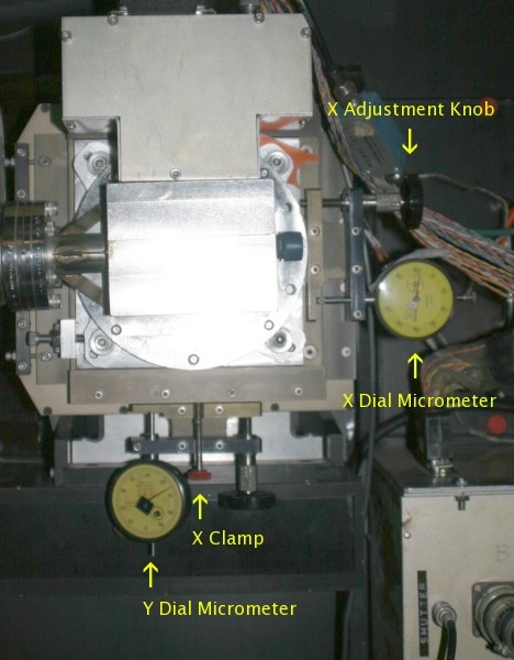
Figure 1: Blue Side X-Y stage
Direct Imaging
A good window for blue direct images with the mirror in the dichroic carrier and the blue x-y stage at the nominal settings is: number of rows (nr) = 325, number of columns (nc) = 325, start row (sr) = 995, start column (sc) = 850. Check it with the top lights, not the TUB lights. When the TUB is at 90 degrees, North is to the right and East is up.Support Astronomers (sa@ucolick.org) Last modified: Thu Jul 17 11:38:14 PDT 2025