Hardware Overview
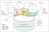
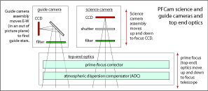
PFCam is essentially a CCD, filter wheel, and guide camera, mounted on-axis above a prime-focus corrector and atmospheric dispersion compensator (ADC). The arrangement of the instrument's hardware components is shown in the 3-D representation below, left, and in simplified form in the schematic representation below, right.

|

|
| 3-D representation of PFCam click for full-size image |
Schematic representation of PFCam click for full-size image |
1. The prime-focus (top-end) optics
The ADC and prime-focus corrector comprise the top-end optics.
The ADC consists of two independently rotating prisms which automatically
adjust to the telescope's altitude and azimuth, correcting the elongating
effect of atmospheric dispersion. The prime focus corrector compensates
for spherical aberration and coma, providing a well-corrected, one-degree
field, only a portion of which is used by PFCam. PFCam has a
field of view 12.6 x 12.6 arcminutes, but may be
somewhat less if using filters other than the 4 inch square broad-band filters.
2. The science camera
The science camera includes filters, shutter, and science CCD.
The filter wheel has six positions, each of which can accommodate a filter
up to 4 inches square (enabling the full 12.6' field to be imaged). 4 inch
square photometry filters are provided by
the observatory.
Any of Lick's collection
of 2" x 2" narrow-band filters can also be used with PFCam, but they
reduce the useful field of view to about six arcminutes.
The science camera assembly moves up and down along the optical axis
to put the CCD at the telescope focus (see "Focusing PFCam" under
Observing Hints).
3. The guide camera
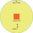
The guide camera views an approximately 1.5 x 2.0 arcminute field, about
thirty arcminutes north of the center of the science field. The
guider assembly can be moved E-W through approximately 12
arcminutes to help find suitable guide stars. The relationship of the
guider and science fields is illustrated in the following diagram:

click for full-size image

click for full-size image
Note: To observe the science target on the guide camera, move the telescope 30 arcminutes south of the target coordinates and position the guider X stage at -140 arcsecond position.
The guide camera is controlled by the telescope operator. The observer may choose to display a copy of the guide camera image with the program "guidercopy," but guiding control remains with the operator. An Rs filter (Spinrad-R night sky filter, see filters). is available from the Motor Control GUI.
Support Astronomers (sa@ucolick.org) Last modified: Tue Apr 10 15:41:08 PDT 2012