Dewar 4 Rotation, Tip, and Tilt Adjustment
Dewar 4 has rotation, tip, and tilt adjustments to that the
CCD can be properly aligned with the Hamilton Eschelle optics.
Figures 1 and 2 show the locations of the adjustment and locking
screws, as well as the micrometers for each axis. Tools needed are
3/32 T-handle allen wrench, 1/4 and 5/16 standard allen, 5/16 open end
ignition wrench.
If you need to adjust the position of the CCD do the following procedure:
- Note current micrometer reading for all three axes.
- Loosen the Rotation Locking Screw (small #4-40 socket head between
dewar lid and front dewar mount bracket).
- Loosen main Lock Screw a few turns.
- Loosen upper hex-headed Y Tip Adjustment using 5/16 open end
ignition wrench by about half a turn.
- Loosen X Tilt Adjustment Screw next to the Rotation Micrometer about
half a turn (1/4 allen wrench).
- Adjust rotation by alternate adjustment of opposing X Tilt Adjustment
Screws (1/4 allen wrench).
- When desired rotation is achieved, tighten the Rotation Locking
Screw (careful, don't strip the thread!).
- Adjust X Tilt by alternate adjustments of the opposing X Tilt Adjustment
Screws.
- Adjust Y Tip using the opposing Y Tip Adjustment Screw (bottom
screw is adjusted with allen wrench trhough hole in bottom of dewar
mount bracket, top screw with the 5/16 ignition wrench).
- When happy with alignment snug opposing adjustment screws slightly
to ensure any slack is taken up.
- Tighten Lock Screw (make this very tight).
- Record micrometer settings for all three axes.
Note: If the dial micrometers are to be left on the dewar assembly, make
sure the dial lock thumb screws are tight. It is suggested that, if over
time, the dewar alignment proves to be stable from one instrument change to
another, the dial micrometers be removed and stored away to less the chance
of damage when handling the dewar assembly.
Useful quantifications of adjustment screw rotation-to-dewar movement:
ROTATION: two full rotations of the X Tilt adjusting screws will rotate the
CCD 1.893 degrees about its optical axis.
X-Y TILT/TIP: one full turn of either X or Y adjusting screws will tilt/tip
the CCD about it center line 0.182 degrees, moving the outer edge of the full
imaging area closer to or further away from the HamSpec field flattener by
about 0.0032 inches.
Caution: Always remember to loosen the Lock Screw and appropriate opposing
Adjusting Screws before making ANY adjustments and re-tighten the Rotation
Locking Screw befoer making X-Y adjustments.
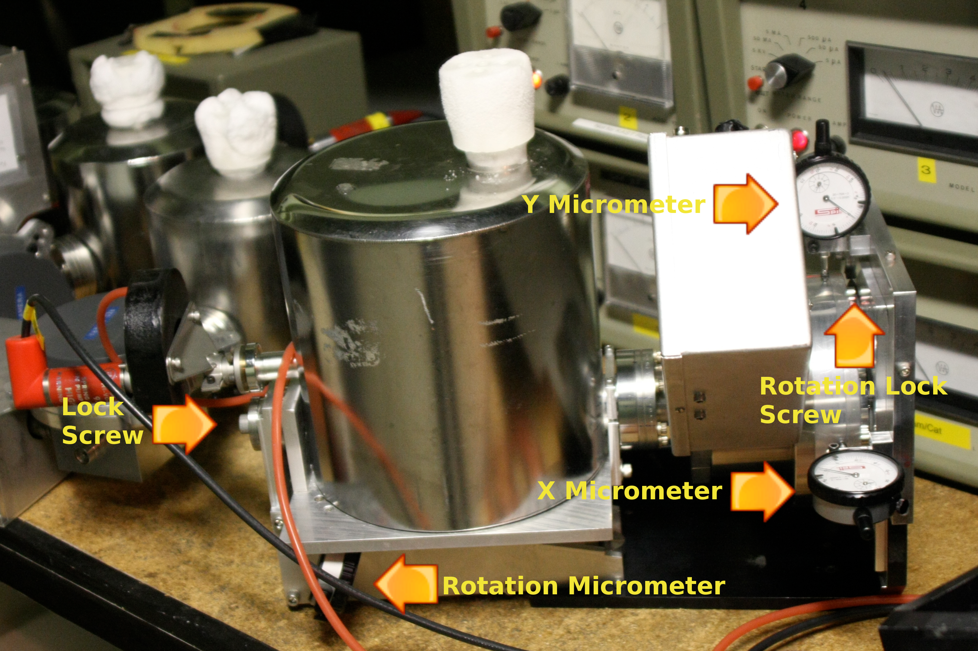
Figure 1: Dewar 4 Micrometer, Locking and Adjustment Screw Locations.

Figure 2: Dewar 4 Micrometer, Locking and Adjustment Screw Locations.
Last modified: Thu Dec 16 19:18:09 PST 2010