CCD Characteristics
As of the first quarter 2012 (beginning 1 February 2012) the dewar 4 CCD is the only detector available for use with the Hamilton Spectrograph. Dewars 6 and 8 have been retired. The dewar 4 CCD is a 4096 x 4096, 12-micron pixel device. The respective readnoise, dark current and QE are given in the table below. (See also detailed characteristics and specifications for Dewar 4.)| Detector | Readout Speed | Amplifier | Gain (e-/DN) |
Readnoise (e-) |
Readout Timea (m:ss) |
Dark Current (e-/pixel/hour @ -80 C) |
|---|---|---|---|---|---|---|
| Dewar 4 | Fast | Right | 0.92 | 3.2 | 0:53 | 2 |
| Dewar 4 | Fast | Left | 0.91 | 3.4 | 0:53 | 2 |
| Dewar 4 | Slow | Right | 0.88 | 2.4 | 2:56 | 2 |
| Dewar 4 | Slow | Left | 0.82 | 2.5 | 2:56 | 2 |
|
aReadout Times for Dewar 4 are for the full
CCD chip using both amplifiers.
Using a single amplifier to read the full chip will take
approximately twice as long.
Other Notes: Dewar 4 is linear in response up to 55,000 DN in all readout modes. Readnoise, gain and linearity measurements were done in Feb 2011. Bias level should be ~1000 DN for all detectors in all readout modes. If it is significantly different contact a staff member. |
||||||
Retired Detector CCD Characteristics
Prior to the first quarter 2012, three CCD's are available for use with the Hamilton: dewars 4, 6 and 8. Their performance and characteristics differed significantly. In addition to the characteristics of the dewar 4 CCD (described above), the characteristics of dewars 6 and 8 are described here in the interests of supporting archival and legacy programs. Dewars 6 and 8 are 2048 x 2048, 15-micron pixel devices.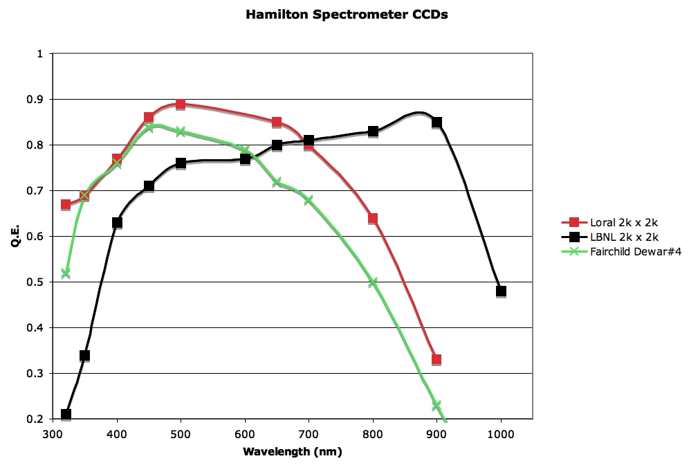
Dewar 6 is Loral 2k x 2k
Dewar 8 is LBNL 2k x2k
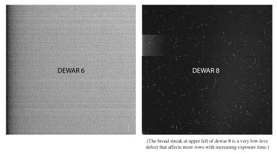
N.B. The QE for dewar 8 in the above plot was measured at -115 c. QE may be slightly lower at lower temperatures. (Statistics courtesy of the Lick Detector Lab) Dewar 6 is a thinned, back-illuminated device with somewhat better blue response, and is much less susceptible to particle events. Dewar 8 is an unthinned, high-resistivity chip with excellent red response and narrower line profiles (narrow-slit FWHM of about 1.45 pixels as compared to about 2.2 pixels for dewar 6), but particle events are much more common and tend to leave longer trails.
| Detector | Readout Speed | Amplifierb | Gain (e-/DN) |
Readnoise (e-) |
Readout Time (m:ss)c |
Dark Current (e-/pixel/hour) |
|---|---|---|---|---|---|---|
| Dewar 8 | Slow | Left | 1.2 | 5.7 | 1:31 | 40 -- 57 (@ -135 C) |
| Dewar 8 | Slow | Right | 1.2 | 10.9 | 1:31 | 40 -- 57 (@ -135 C) |
| Dewar 8 | Fast | Left | 1.3 | 10.1 | 0:31 | 40 -- 57 (@ -135 C) |
| Dewar 8 | Fast | Right | 1.3 | 17.0 | 0:31 | 40 -- 57 (@ -135 C) |
| Dewar 6 | Slow | Right | 1.1 | 10.0 | 1:31 | 16 (@ -118 C) |
| Dewar 6 | Fast | Right | 1.2 | 18.0 | 0:31 | 16 (@ -118 C) |
|
bDewars 6 and 8 each have two readout
amplifiers, of which only one is used at a time to
read out the CCD.
It is highly recommended to use the Left amplifier for
each detector, as it has significantly less readnoise.
cReadout Time is for the full CCD chip and does not include a special erase of the chip after readout for dewar 8 (special erase takes 8 sec). The time to erase the Dewar 8 CCD before the exposure begins is ~13 seconds for slow readout, and ~8 seconds for fast readout. Other Notes: Dewar 6 left amplifier is not functioning as of December 2009. Dewar 8 measurements made during Jan 2009, dewar 6 during Apr 2009 by T. Lowe. Dewar 6 slow readout measurements made by R. Stover Jan 2010. Bias level should be ~1000 DN for all detectors in all readout modes. If it is significantly different contact a staff member. |
||||||
Support Astronomers (sa@ucolick.org) Last modified: Wed Nov 28 19:00:00 PST 2012