Lick Infrared Camera User's Guide

Description

Figure 1. is a 3-D representation of the instrument's light path and principal components.

The optical interface, outlined in green in Figure 1., bolts to the telescope and supports the camera's other components. A dichroic beamsplitter reflects the infrared part of the telescope beam to the dewar, where it is filtered and reimaged on the array by the dewar's internal optics. The visual part of the beam is transmitted by the beamsplitter and reflected by two plane mirrors to the boresite camera for acquisition and guiding.

The TUB diagonal and TUB camera are permanently mounted on the telescope above LIRC-II's optical interface and below the primary mirror. While not parts of the instrument itself, the TUB components may be used with LIRC-II for acquisition and guiding.

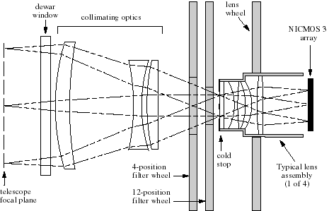
Figure 2. Dewar Optics

Figure 2. above illustrates the dewar's internal optics. The telescope focal plane lies approximately 70-mm in front of the dewar window. Just behind the window, a three-element lens assembly collimates the beam. This is followed by independentally positioned "front" and "back" filter wheels with four and twelve positions respectively. Table 1. below lists their contents. Filter transmission curves can be found elsewhere in thei manual.

Table 1. Filter Wheel Contents
Back Filter Wheel
FilterBandpass or
Central Wavelength
at 77 ° K
K1.98 to 2.39
J1.10 to 1.44
Open -
OII1.237 (within 1%)
FeII1.644 (within 1%)
H2 S(I) 1-02.122 (within 1%)
Brackett Gamma2.166 (within 1%)
H2 S(I) 2-12.248 (within 15)
CO2.295 (within 3%)
K-prime1.95 to 2.35
H1.50 to 1.82
Darkbetween filters
Front Filter Wheel
FilterBandpass or
Central Wavelength
at 77 ° K
Open -
ND22% transmission
Open -
Open -
Darkbetween filters
The lens wheel carries four lens assemblies which reimage the focal plane on the detector at three different plate scales. Three of the lenses provide the narrow, intermediate, and wide fields of view; the fourth, or A/O lens, is identical to the narrow field lens but has an f-30 cold stop for use with the Adaptive Optics instrumentation at the 3-meter. The other lenses have f-17 cold stops to match the 3- and 1-meter telescopes' normal cassegrain beam. These stops serve to block thermal radiation from the telescope structure and dome. The intermediate field of view also includes a cold central spot which blocks the shadow of the secondary mirror and is also important when checking the camera's collimation.

Figure 3. below shows the globular cluster M97 as it appears on the array at the 3-meter telescope, with each field of view. Field size and plate scale are given for each of the three lenses at each telescope. North is at bottom, East at left, on the data-taking system displays at both telescopes.
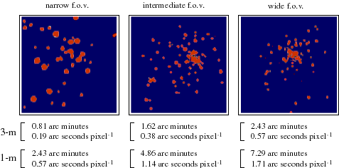
Figure 3. LIRC-II Fields of View and Plate Scales

The observer opeartes the instrument from the telescope control room via the data-taking, motor control, and "lirctop" programs, all of which run in X-windows on the user's terminal. Figure 4. shows how the various parts of LIRC-II and its associated systems fit together.
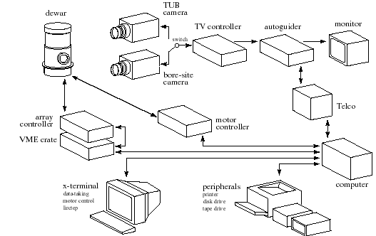
Figure 4. LIRC-II system integration

The data-taking program permits the user to input observing parameters, control the array, provide information for the FITS header, and control data recording. The motor-control program operates the lens and filter wheels and the moveable dichroic beamsplitter. Lirctop is a collection of Vista routines which automate various observing procedures such as dithering, mosaicing, and calibrating. The links in this paragraph lead to detailed guides for these programs.

The bore-site and TUB guide cameras share the same standard Lick TV camera controller. Either can be used for acquisition and to provide the signal for the Lick autoguider, however, the two cameras differ in some important respects. Choosing the best TV camera is discussed in the section on Acquisition/Guide Cameras.

Output devices for LIRC-II data include an X-Window terminal, high-capacity disk drive, 8-mm Exabyte tape drive, and a laser printer.